KYROFLUX MANUAL
- KYROFLUX 메뉴얼
High Definition Flux Sampler for USB
© 2009–2021 István Fábián and KryoFlux Products & Services Limited
KryoFlux DiskTool Console (DTC) and KryoFlux firmware engineered and written by István Fábián; additional product design and documentation by Christian Bartsch; Linux port by Adam Nielsen; macOS port by Alexander Coers; Amiga OS 4 port by Marcus Comstedt; DiskTool Console UI by Kieron Wilkinson; hardware layout by Lars Reichel, Stefan Herzog and Olimex Ltd; Logo by Christian Krapp; project support by the Softpres team.
Original hardware design "Cyclone20" and proof of concept by Richard Aplin Thanks to our beta testers, especially Dirk Verwiebe. Additional thanks to Jean-François del Nero, Toni Wilen, those we forgot to mention and the communities of English Amiga Board (http://eab.abime.net) and Amiga & Phoenix Community (http://a1k.org) for morale, support and ideas.
Manual Revision 1.26, DTC version 3.00 (2021-3-18)
www.kryoflux.com | forum.kryoflux.com
For commercial use: kryoflux.com/licensing | licensing@kryoflux.com
Disclaimer:
This is commercial software, which is free for private, non-commercial use. Please see licence.txt for detailed information. The hardware design itself is free to explore and experiment with. Notwithstanding of the terms of the licence you are allowed to change, modify and improve the hardware design provided as long as you make your changes public and freely available as well. The design may not be ex-ploited commercially (e.g. PCBs or assembled units sold where money is changing hands, regardless of profit) unless approved by us. Individuals interested in building and/or labelling the the hardware as “KryoFlux” and/or “designed by Softpres” must get prior written approval. This is to make sure an official hardware layout is used to prevent people from buying broken hardware associated with our name and trademarks. The Software Preservation Society, Softpres and KryoFlux are trademarks of The Software Preservation Society and KryoFlux Products & Services Ltd. The following information is provided as is. Any hardware made according to the enclosed schematics is built at the user’s own risk. There are no guarantees that the information contained herein is complete or correct. KryoFlux is a registered trademark of KryoFlux GmbH. Used with permission. All (registered) trademarks are the property of their respective owners and are used for informational purposes only.
Usage:
Read, convert, store and write contents of various legacy disk formats, including but not limited to: Acorn Electron, Apple, Amstrad CPC, Archimedes, Atari 8-bit, Atari ST, BBC, Commodore 64, Commodore Amiga, MSX, IBM PC, PC-8801, Sam Coupe, Spectrum, E-MU Emulator II and many others that were stored on a 3", 3.5", 5.25" and 8" media.
Preface:
KryoFlux by definition refers to the concept of the following project as well as the hardware design itself. While exact details on the hardware and the design are contained in the hardware section below, one should note that KryoFlux is based on the concept of having a small interface adapter using an ATMEL ARM CPU doing the actual sampling. The software side is divided into a dedicated driver for various flavours of Windows, the DiskTool Console (DTC), a flexible software for capturing flux transition data, and the firmware for the ARM board.
Introduction:
While today’s computers store data on huge hard disks, optical media or even now solid state drives, legacy computers utilized cassettes and floppy disks. Whereas data stored on compact cassettes can be easily sampled using a tape recorder and a sampling device, like a standard sound card found in any modern PC, floppy disks have several shapes and sizes and even more ways to actually store the data on them. Standard PC floppy controllers actually try to interpret and analyse the data before handing it over to the operating system. While some controllers can be tricked into delivering more “raw” data as they should, most of them simply can not be used to read anything but IBM PC compatible formatted media using MFM coding.
KryoFlux replaces any standard controller and makes data from an attached disk drive available as a flux data stream.
Every magnetic disk, regardless of type or size, stores data by changing the orientation of ferro oxide particles bound onto a durable and flexible plastic platter. The data itself is represented as “flux transitions” aka “flux reversals” which indicate a change of the polarity of the magnetic field. Because it is impossible to actually read the orientation of the particles on the disk surface using the head designs used, the only way to define data is by flux changes. This requires the disk to be spinning because without movement, no AC current is induced in the head. The actual data is normally coded using a scheme like FM, MFM or GCR. While MFM is the most popular scheme (in fact it just survived long enough) used on floppy disks, there are many other ways to encode and represent logical 0 and 1. Error detection and error correction is beyond what is stored in fluxes – both need interpretation of the signal and knowledge about the scheme used for writing to determine if the readout is correct or not.
While optical media produced in a pressing plant can last for ages so to speak, magnetic media has a proven life span somewhere between five to 30 years, with the latter only applying to media which was stored under ideal conditions. The higher the capacity of the platter, the higher the risk of the media failing early.
System Requirements:
Computer with 32bit or 64bit flavour Windows (Vista or later), macOS (10.5 or later), Linux or Amiga OS 4; Dual Core, Atom or equivalent processor running at 1.6GHz or more; 1GB of RAM; a native USB 2.0 port; free hard disk space to store tools (~10MB) plus dump data. For best results, KryoFlux must be attached directly to the computer without any hubs or cable extensions inbetween. Due to the precise timing required, results with hubs can be mixed with the possibility of complete failure as well!
You also need a floppy disk drive with a standard 34 pin connector. Please note that KryoFlux was mainly developed for HD 3.5” (“1.44MB”) and HD 5.25” (“1.2MB”) drives. It also works well with selected 3” (e.g. Amstrad FDI-1) and 8” (e.g. Shugart 851; might require additional adapter) drives. There is a broad range of variants, with some “dinosaurs” not being very keen on standards. It is therefore possible that certain brands or models, especially old drives, may not work with the board. Solutions range from modifying software to modifying hardware.
This manual deals with the pre-built and fully assembled board distributed by KryoFlux Products & Services Limited. You can buy the unit directly from us via kryoflux.com. Please note that only units sold by KryoFlux Products & Services Ltd come with support (as indicated).
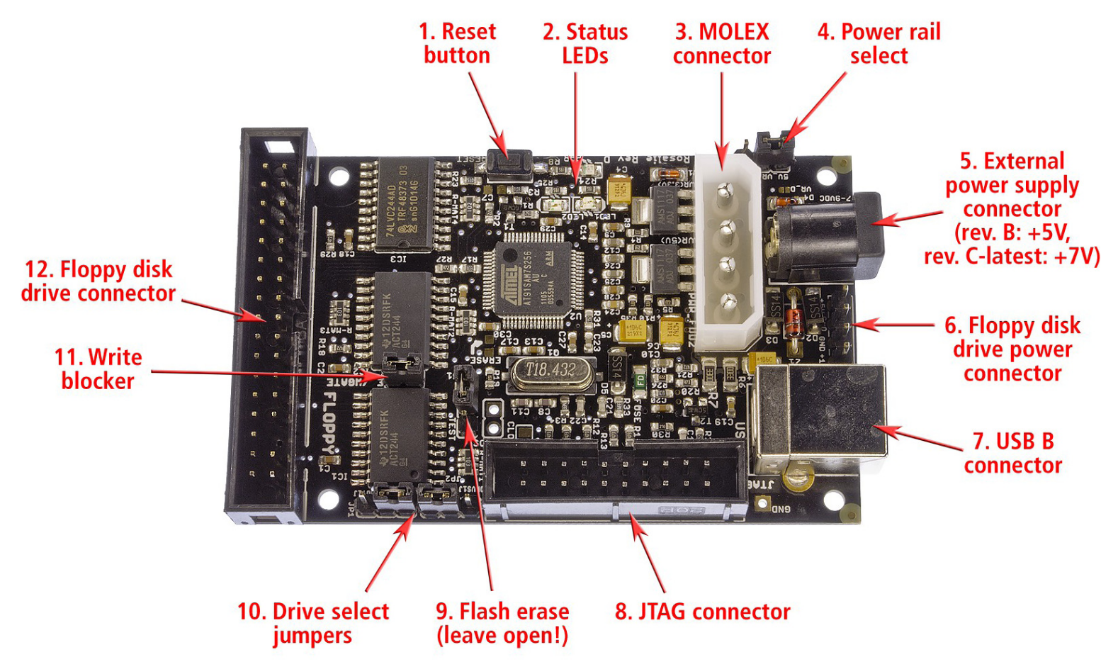
KryoFlux Harware overview
(1) Reset button: If the board does not function or hangs after usage, press this button to reset the board.
(2) LEDs: There are three LEDs on the board. The LED on the upper right (red) should light up all the time when the unit is on. The LEDs to the lower left and right (yellow and green) are off as long the unit has not been used in a session. As soon as the firmware has loaded, the LEDs start to fade alternatingly. The green LED signals firmware activity, while the yellow one indicates an active USB connection.
(3) MOLEX power connector: KryoFlux is a fully bus powered device. Therefore no external power is needed. For special purposes the board allows to be powered externally. It is even possible to distribute power to an attached device (see 5.). Please note that the power rail for +5V is directly connected to the device’s CPU. A bad (cheap, unreliable, broken) power supply can damage your board as well as external devices. The PSU must deliver a minimum of 1A per power rail (+5V/+12V). Check the orientation before attaching the plug. Incorrect orientation of the cable will DESTROY your KryoFlux board and/or your drive. You will also void your warranty (prebuilt boards).
(5) DC power connector: Standard power connector to supply +5V (rev. B board) or +7 to +9V (rev. C board and later; will internally be transformed to +5V) DC to the board (if desired). Useful when powering a 3.5” drive through the board, as these usually don’t need +12V. The PSU must deliver a minimum of 1A, tip is hot, shield is ground. Do not connect more than +5V DC to a rev. B board or more than +9V DC to a rev. C (or later) board! You will destroy the board and other equipment as well. You will also void your warranty.
(6) Berg power connector to power a drive – or two with y-cable – via the board: You must use standard Berg connectors (also – incorrectly – referred to as Molex mini) to connect the drive to the board. On the picture above, +12V DC is to the bottom, so the yellow cable of the connector MUST face to the bottom as well, with the red cable facing up (+5V DC). Incorrect orientation of the cable will DESTROY your KryoFlux board and/or your drive! You will also void your warranty (prebuilt boards).
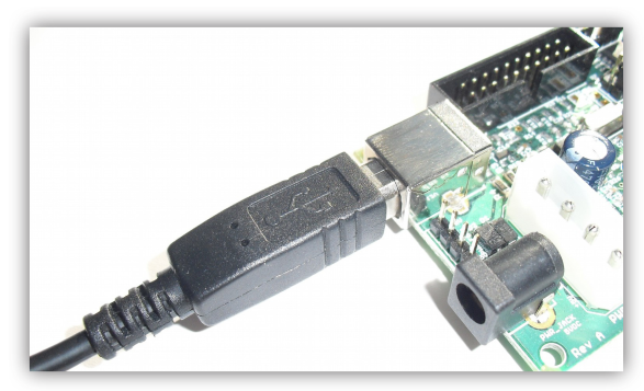
(7) USB B connector: KryoFlux connects to the computer with a USB A to USB B plug. The board (NOT an attached drive!) is solely powered through USB.
(8) JTAG connector (not used): This connector is for development purposes and advanced servicing only and can be ignored.
(9) Firmware erase jumper: KryoFlux uses an ATMEL CPU as the core of its system and can be booted from internal flash memory. KryoFlux does not flash firmware onto the device. Instead, it is downloaded at the beginning of each session (it’s so fast, you won’t even notice). If some other application accidentally writes something into the flash, unplug the device. Set the erase jumper to on. Connect the device, wait at least ten seconds. Now unplug the device and set the jumper to off again. KryoFlux is now back to normal.
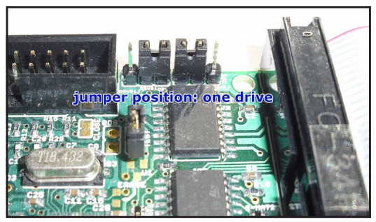
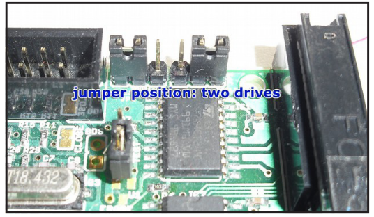
(10) Drive select jumpers: Floppy cables usually have two sections for connecting drives, each of them has two connectors (one for 3.5” drives, the other one for 5.25” drives). You must only connect one drive to one section at a time. The section where the cable is twisted over (at the very end of the cable) is for drive 0 (which used to be drive A: in PCs). The other section is for drive 1 (which used to be drive B: in PCs).
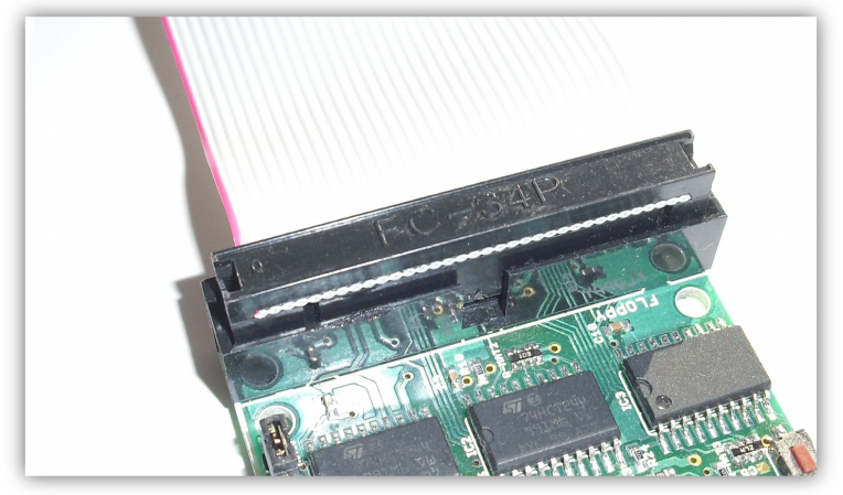
(12) Floppy disk drive connector: This socket is for the other end of the drive cable. If it has a small nose, make sure its orientation matches the gap in the socket. If not, please check for pin 1, which is marked. Make sure line 1 (usually signalled by a colored cable) is pointing towards the drive select jumpers (no. 8).
Power rail select:
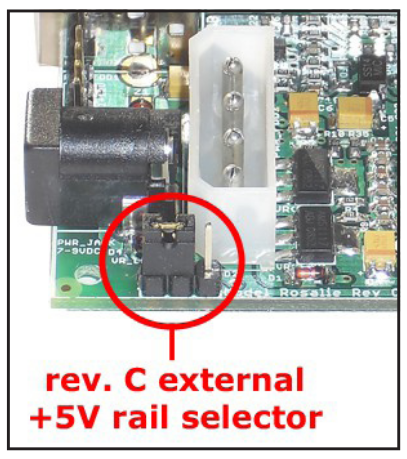
Revision C and later of the KryoFlux board come with a regulated external +5V power rail. All external power that is fed into the board via the MOLEX (3) and DC power (4) connector is regulated for a stable +5V DC power supply. This can come in handy for special usage scenarios and will also ensure that the bus driver ICs are operated at precisely +5V. While the DC power connector is always regulated (therefore rev.C boards or later need +7V to +9V DC present at the DC power connector), the routing from the MOLEX connector can be adjusted via a jumper. The setting on the left will transform +12V to precisely +5V. The opposite setting will route +5V or whatever is present at the +5V rail of the MOLEX connector. This rail has no protection diode, so be sure to not experiment with polarity. More than +5V DC or wrong polarity will fry your board! We recommend keeping the jumper at the position shown on the picture at all times.
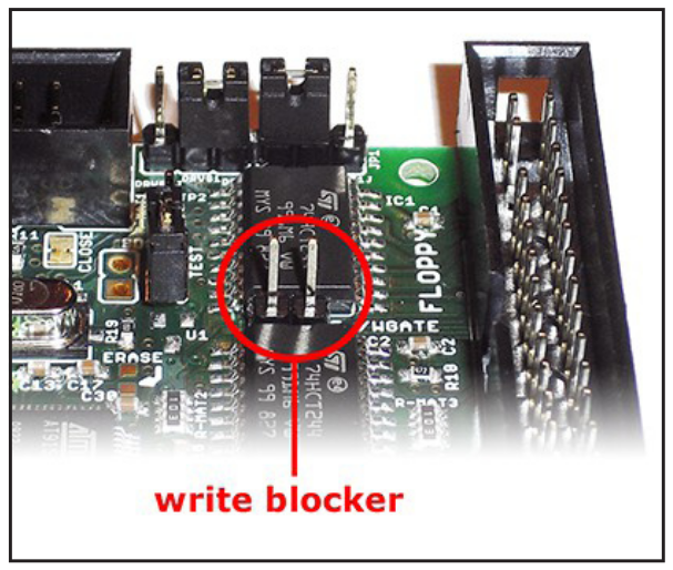
(11) Write blocker: With the introduction of writing to the KryoFlux host software (DTC) and firmware, protection of media on the hardware level became necessary. The commercial marketplace offers special devices that can be put between a floppy disk drive and a controller to prevent accidential writes. This functionality has been added to the KryoFlux hardware.
Revision D and later offer a built-in write blocker. The write block can be enabled by removing the jumper for WRITE GATE. After it has been removed KryoFlux can not write to disk, regardless of media and protection tab. Putting the jumper in place will enable writing again. The picture shows the board with the write block enabled. If you are using KryoFlux in a preservation environment at an archive, library or museum we strongly recommend setting this jumper as shown. This setting can not be circumvented in software.
Using a so-called “flippy”-modified floppydrives
There currently exists two versions of this modification/drive:
Version #1 (“Panasonic”) works by modifying the drive so that it can step into the negative domain and access a virtual track -8 on the upper head – which is the location of track 0 of a “flipped disk” written with a single headed drive. Note: During a dump you’ll see a message that says “00.0 : Control Command Rejected by the Device” - When you see this, it means the read/write head has moved to the normal side (see below) of the track 0 sensor. This drive can also be used like a standard drive with a standard controller as well.
Version #2 (“Teac”, “Newtronics”) works by re-aligning track 0 to -8, meaning that it is permanently track-shifted, so data read off standard disks will need to be adjusted in software. Version #2 drive does therefore no longer work with a standard controller. Since the Teac and Newtronics do not bypass the track 0 sensor, neither are prone to getting stuck in the negative domain.
| WARNING
Floppy disk drives tend to self-initialize at powerup, e.g. by doing a seek to track 0, which will activate the track 0 sensor (“/TRK00”). When using version #1 disk drives, stopping a dumping process while the drive is below track 0 (reading between -8 and -1) will leave the drive in an undefined position. If the drive is left undefined, the next access (with a seek for track 0) will move the head further back (“outwards”) until it reaches a mechanical barrier. This will result in “banging”, a loud rattling sound, which might misalign or further damage the drive. If you hear such sound, remove power immediately. The drive can then be carefully repositioned by turning the motor spindle which moves the head. DO NOT PUSH the head carriage itself! NOTE: Starting from DTC version 2.72, if the dumping process is interrupted by means of software (ie. ctrl + c), the head carriage will be repositioned back to track 0 regardless of its current position. ersion #1 drive must be the only device on the Shugart bus (=connected to KryoFlux) OR any other drive connected (only one modified drive per bus) must not have contact to pin 33 (usually ground, used here for TRK00 bypass). Also, regardless of what the manual might say, KryoFlux must be powered (=connected to USB) before the drive itself is powered. Otherwise track 0 might become “invisible” for the drive. In both scenarios the drive will bang its head against the mechanical barrier trying to find track 0. |
Note: This drive is by definition to be used with the KryoFlux floppy disk controller only. Chances are that, depending on brand and model, the drive will work with other controllers. However, such operation cannot be guaranteed.
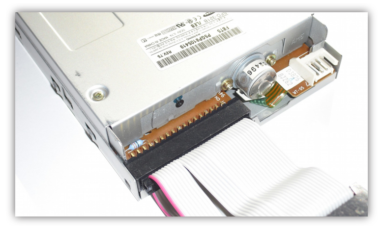
Drive can be connected to the KryoFlux with the supplied (if bought with a KryoFlux) or a standard floppy disk data cable. Please note that the data connector on the PCB has a marking for data line #1 which must be aligned with the red (or otherwise coloured) stripe of the data cable. As outlined above, Version #1 must be the only drive on the bus or any other drive must not connect to data line 33 of the drive data cable, as this signal is used to control the negative track stepping feature.
Damage caused by scenarios outlined above is exempt from warranty.
Setting up the hardware
Important! Always make the drive – board - connection first, then plug the power (PSU & USB). Power always comes last! You are connecting two systems with different grounds, so ground (connected via the floppy data cable) must always come first. Never ever connect or remove the floppy data cable while the drive and / or the board are still powered. Doing so will void your warranty and you risk damaging drive and board. You have been warned!
Place the KryoFlux board and the disk drive on a flat, non-conductive surface. Make sure you will not short circuit the device by placing it on a metal table or similar. Connect KryoFlux and drive with floppy data cable.
Always unplug and disconnect from mains when not in use! Do not leave unattended!
Check for correct orientation, the marked wire (usually red or white) signals data line 1. With the board facing towards you and the floppy connector on the upper end, data line 1 is on the left.
Usually, pin 1 must face left when looking at the drive from above with the drive pointing away from you. Still, double check! Depending on the package, KryoFlux comes with or without cables and a PSU. We recommend powering the drive directly with the external PSU. It is possible to route the power through the board, especially, if you happen to have two drives and only one PSU. You are doing this at your own risk. Please keep in mind that a malfunctioning PSU could destroy your board because of voltage spikes. Connect the drive to the PSU with the Molex plug (if you have a 3.5" drive, you need to attach the Berg adapter to the Molex plug), or the PSU to the board and the board to the drive with a Berg to Berg cable or Berg to Molex cable. Again, we strongly recommend directly powering the drive.
For normal operation, always connect the board to the computer first, then plug in an external power supply. Otherwise you might lock up the board. Simply unplug USB and power, and restart with USB.
Do not power the PSU yet! Do not connect the USB plug to the computer yet!
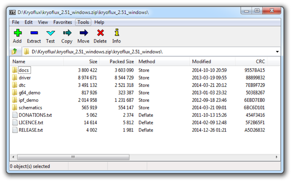
Unpack the software archive available from the KryoFlux web site (http://www.kryoflux.com).
Windows: Copy the appropriate version (32 or 64bits) of DiskTool Console (DTC.exe, firmware.bin, CAPSImg.dll) to a location of your choice. Also take note of the location of the "driver" folder, as it will be needed to complete the following steps.
macOS: Just run the installer (KryoFlux.pkg). This will install DTC as well as libusb. The installer includes a text file that contains a list of files and folders installed should you want to remove them later. Please connect the computer and the KryoFlux board with a USB cable (no USB hub!) and continue reading on page 8 ("All platforms again").
Linux: Copy the DiskTool Console (DTC32 or DTC64, firmware.bin) to a location of your choice. Please install libusb 1.0.8 (available separately, chances are it's already installed as this is a popular component). Please connect the computer and the KryoFlux board with a USB cable (no USB hub!) and continue reading on page 8 ("All platforms again").
Amiga OS 4: Copy the DiskTool Console (DTC, firmware.bin) to a location of your choice. Copy capsimage.device to "DEVS:". Please connect the computer and the KryoFlux board with a USB cable (no USB hub!) and continue reading on page 7 ("All platforms again"). Note that there is no Java VM for the Amiga (yet), hence you can not install the GUI.
Attach the USB cable to KryoFlux and then attach it to your computer. Do not use a USB hub!
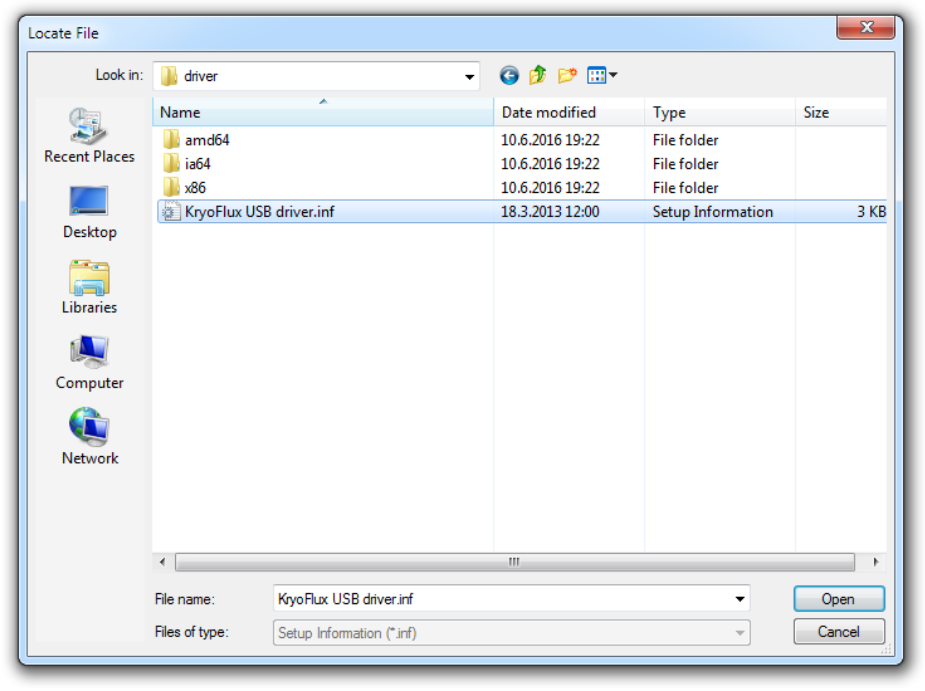
Open Device Manager and check under LPT & COM ports that a device called "Bossa" pops up. Older versions of Windows might just show an unknown device. Right click the "Bossa" (or unknown) device and choose to update driver. Then choose to pick the drive yourself from a list. Click to "Have disk", then navigate to the drivers folder in the KryoFlux folder and pick the KryoFlux driver. Make sure to instruct Windows that you will pick the proper driver; Windows might insist on the Bossa driver being the right choice.
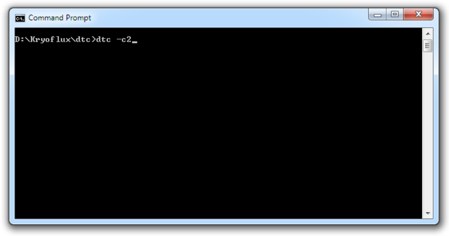
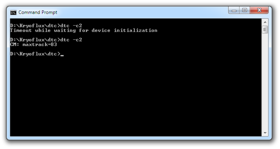
Open a command line (Start Menu, "Run") and change to the folder where DTC resides. Enter "dtc -c2".
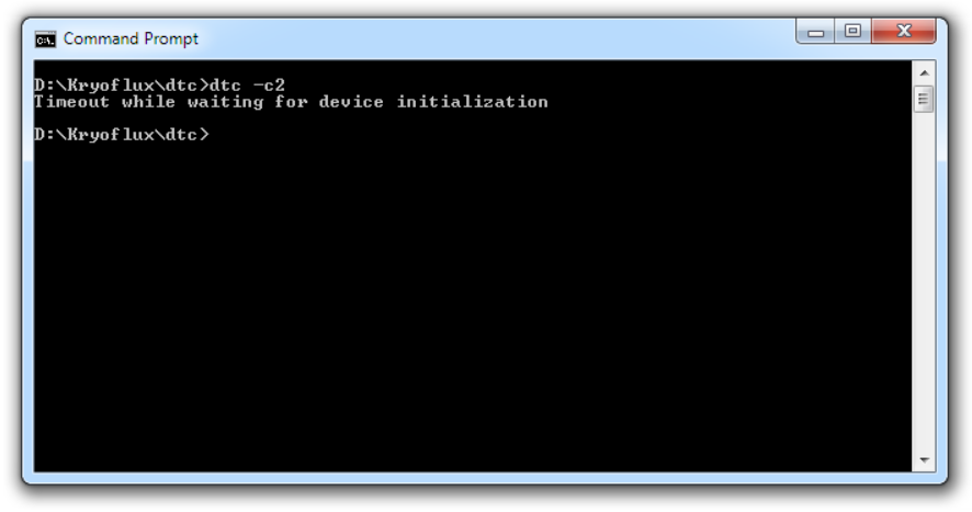
The device will re-enumerate, so Windows has to install another instance of the driver. Please follow the same procedure mentioned above. DTC will report an error, which is expected due to the driver being installed.
All platforms again:
Plug the PSU into mains.
Enter "dtc -c2" (again). DTC will now check for the maximum track your drive can access. Depending on the drive type this seeking might fail; this usually does not interfere with standard operation.
KryoFlux is set up. Congratulations! Versions of Windows 10 tend to automatically install the "Bossa" device again. In this case, right click and choose to replace driver manually as instructed earlier.
Using the GUI:
If you are not familiar with command line programs, we recommend you start with the GUI first to get a feel for how KryoFlux works. Technically speaking the GUI sits on top of DTC, the command line tool, which means whatever you can do with the GUI, can be done with DTC, too. Strictly separating functionality from the interface means all power of KryoFlux is also available via preservation frameworks and KryoFlux can work fully automated, e.g. via batch files or other external control mechanisms. The GUI is a multi-platform application written in Java. You might need to install the Java Virtual Machine on your computer if you haven't used Java applications before. We recommend you also read the chapter about DTC even if you don't plan using it right now, as it contains valuable information. Double click "kryoflux-ui.jar" to start the GUI.
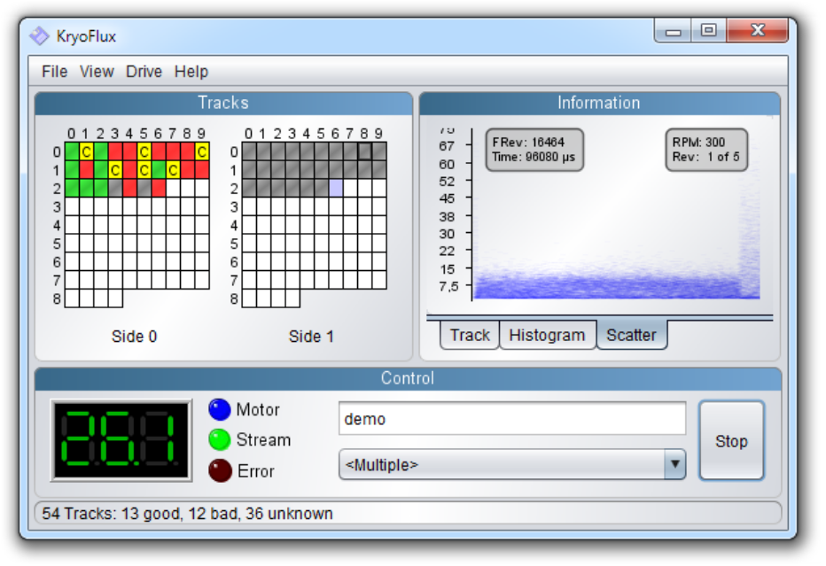
The GUI is separated into three sub-windows. The upper left window contains the track grid. Each block of the grid represents a track on the disk's surface. The upper right window contains the track info block, with two more tabs called "Histogram" and "Scatter". The lower part of the GUI is the control section, where the current track, drive controls and the filename are displayed. Below the filename is the format selector, which itself is dependent on so called profiles. The complete last line of the window is the status line which displays additional information.
The track grid shows the maximum 84 possible track positions available on a disk, which means accessing 40 track disks will only use every second block. As a specialty, some 40 track designs, e.g. the floppy drive used for the Commodore 64, the 1541, actually make use of 80 track mechanisms which can be used by copy protection schemes. So don't be surprised if dumping with a certain format switches to 80 track mode. When you start dumping the complete grid gets filled with white. During dumping, blocks change their color according to the result of the process.
- green - track decoded, no errors found
- grey - noise (or unknown encoding scheme)
- red - track decoded, error(s) found, reading will be retried
- yellow - notifications and warnings, e.g. additional header data found
- glowing - track is being dumped
To get more information about the result of a certain track, move your mouse pointer over it. This will output the result of the operation in the status line.
The histogram and scatter views are only available if dumping stream files. While displaying the scatter data (starting at the index), pressing the function keys F1 to F5 will display the corresponding revolution (if present). Pressing "a" will automatically animate consecutive revolutions in the scatter view. "r" increases the RPM by 5 at which the track graph is being interpreted, shift-r decreases the RPM by 5. Pressing "i" will toggle the small info field placed in the scatter. Please note that real time decoding of data dumped needs resources which might make dumping troublesome on slow computers. If this turns out to be the case, just switch to the "Track" display.
The menu bar contains the menus "File", "View", "Drive" and "Help".
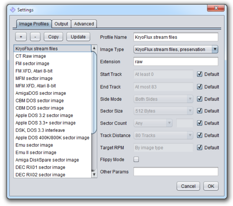
The file menu contains the settings. Among these settings are the so called profiles. A profile defines how a disk should be dumped. A profile is nothing else than a combination of command line parameters which are automatically set by the GUI according to the profile characteristics.
The good news is that Profiles can be cloned and edited which means that you can prepare specific settings for whatever task you have in mind. Please also note that several profiles can be used at the same time while dumping, meaning that a combination of stream files and e.g. AmigaDOS will create a perfect dump environment where the guide format (AmigaDOS) will make DTC retry if an error is found during decoding, delivering perfect stream files, even if these only contain raw data. This is actually the best of both worlds - verified raw and decoded image data.
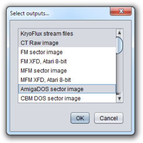
To use multiple output formats at the same time, select "<multiple>" as shown in picture of the main window above. This will open a pop up window which will then let you select the profiles required.
To create stream files and apply preservation parameters for an Amiga disk to be dumped, select "KryoFlux stream files", then add "AmigaDOS". "CT Raw image" can be omitted starting with release 2.20. It is only needed if you intend to export data for inspection with the Softpres Analyser (CTA; available separately) afterwards.
Before you start creating your first dump, please switch to the "Output" tab an select the destination directory. The GUI will create subfolders for stream files, all other files will be named as per your filename selection with the corresponding extension added.
The "View" menu offers a separate scatter window which will be floating atop. This is handy if you have a large desktop and want to display track information or histogram data and keep an eye on the bands used for encoding.
The "Drive" menu will let you select the drive to be used for dumping. KryoFlux supports two drives, as used in most PCs back in the 1980s and 1990s. A drive needs to be calibrated before it can be used, which will be used to determine the maximum track accessible by the drive. There is no need to put a disk into the drive while calibrating.
-> In the unlikely event that calibration fails and you are using the fast firmware, you might want to try using the slower (standard) firmware which was specifically tuned for 8", 5.25" and 3" drives. Close the GUI, copy the file "firmware.bin" from the installation ZIP to the GUI directory, replacing the faster firmware file. Don't forget to reset your KryoFlux board and restart the GUI. It will now use the slow firmware.
If you have changed a drive or the calibration failed, you will need to recalibrate the drive, which is why it's listed as a separate option in this menu.
One key feature of KryoFlux is that decoding can be "replayed". You can therefore select "stream files" as a floppy drive in the menu. This will give you the option to create other images from a STREAM dump made earlier.
Note: The GUI currently does not support writing to disk, please use the command line tool DTC to write images back to disk.
Using DTC:
DTC is a command line application with an optional graphical user interface (GUI) that runs on the Java Virtual Machine. The GUI is located in the DTC folder and can be used after necessary drivers have been installed. The GUI will take care of most tasks, but currently is not as versatile as the command line version.
DTC is the "DiskTool Console" and therefore controls all functions of the package. One special feature of DTC is to output several images at once. That means you can e.g. dump an Amiga game disk to stream files (raw files) while at the same time writing an .ADF of the sector data to see if the disk has a standard file system. You don't have to redump the same disk if you find the disk has some kind of protection which can not be represented in a standard sector dump file (e.g. ADF).
You’ll find it even more convenient to know that DTC can generate all further disk images (image type 2 or higher) without a disk present. All you ever need to keep are STREAM or DRAFT files. This option is called "deviceless" mode and means it even works without the KryoFlux hardware present. Think of this as a converter mode, where DTC will operate on a virtual disk, based on a stream dump made earlier.
The only difference between KryoFlux stream files (image file type 0) and KryoFlux DRAFT files (image file type 1 - to be implemented later) is that the latter is a convenient one-file only device-independent image that is handy for transportation, while the former is a group of files representing uncompressed raw data, one for each track and side. This can be more comfortable for development of converters and similar. Please note that generation and usage of stream files should be preferred.
DTC offers the following command line options:
-f<name>: set filename
-i<type>: set image type
-m<id>  : set device mode
          1=image file, 2=KryoFlux (Model: Rosalie) (default 2)
-d<id>  : select drive (default 0)
-dd<val>: set drive density line (default 0)
          0=L, 1=H
-l<mask>: set output level, add values to define mask (default 62)
          1=device, 2=read, 4=cell, 8=format, 16=write, 32=verify, 64=TI
-r<rev> : set number of revolutions to sample (default by image type)
-t<try> : set number of retries per track, min 1 (default 5)
-tc<try>: set number of retry cycles per track, min 1 (default 2)
-tm<try>: treat missing sectors as bad sectors
          0=off, 1=on (default on)
-a<trk> : set side 0/a track0 physical position (default 0)
-b<trk> : set side 1/b track0 physical position (default 0)
-s<trk> : set start track (default at least 0)
-e<trk> : set end track (default at most 83)
-g<side>: set single sided mode
          0=side 0, 1=side 1, 2=both sides
-z<size>: set sector size
          0=128, 1=256, 2=512, 3=1024 (default 2)
-n<scnt>: set sector count
          0=any, +Z=exactly Z, -Z=at most |Z| (default 0, by image type)
-k<step>: set track distance
          1=80 tracks, 2=40 tracks (default 1)
-ks     : use only selected tracks during analysis (default auto)
-v<rpm> : set target system's drive speed, RPM (default by image type)
-x<mode>: set extended cell band search (default by image type)
          0=image only, 1=all, 2=reference only
-y      : set flippy disk mode
-oo<ord>: output image track order, add values to define ord (default by image)
          1=side 0 descending (side 0 ascending if 0)
          2=side 1 descending (side 1 ascending if 0)
          4=side 1 then side 0 (side 0 then side 1 if 0)
          8=side oriented (track oriented if 0)
-os<trk>: output image start track (default by image)
-oe<trk>: output image end track (default by image)
-ot<pct>: data band threshold (default 30)
-p      : create path
-c<mode>: read calibration mode
          1=track read, 2=maximum track, 3=RPM

-pg<type>: plot: graph type (default 0)
          0=no graphs, 1=sample, 2=consistency
-pf<mode>: plot: flip mode (default 0)
          0=off, 1=side 1, 2=both sides
-pw<size>: plot: graph width (default 800)
-ph<size>: plot: graph height (default 600)
-px<fval>: plot: graph x origin (default 0.0)
-py<fval>: plot: graph y origin (default 0.0)
-pd<fval>: plot: graph domain (default 0.2)
-pr<fval>: plot: graph range (default 0.000020)

-w       : write image to disk
-wi<type>: write: set source image type (default 0)
-wp<par> : write: set platform specific parameter (default 0)
-wm<mode>: write: set mode, add values to define mode (default 0)
-wy      : write: write side 1 to side 0, side 1 becomes unformatted
-y       : write: -wy for flippy disks imaged in a single pass
-g<side> : write: select sides to write (default auto)
          0=side 0, 1=side 1, 2=both sides
-k<step> : write: set track distance preference in source image
          1=80/all tracks, 2=40/even tracks (default 2)
-ks<step>: write: enforce track distance; disables crosstalk filter
-wg<side>: write: enable unformatted side filter (default 3)
          0=disable, 1=side 0, 2=side 1, 3=both sides
-wk<side>: write: enable track crosstalk filter (default 3)
          0=disable, 1=side 0, 2=side 1, 3=both sides
-wv<mode>: write: verify (default 1)
          0=off, 1=verify
-ww<ns>  : write: precompensation window in ns, max 10000 (default auto)
-wt<ns>  : write: precompensation time in ns, max 1000 (default auto)
-wb<bias>: write bias (default by image)
          0=neutral, 1=bias out, 2=bias in
-we<mode>: write: erase mode (default by bias)
          0=normal, 1=used only, 2=wipe
Image types supported for reading from a disk:
 0 : KryoFlux stream files, preservation
 0a: KryoFlux stream files, format guided
 2 : CT Raw image, 84 tracks, DS, DD, 300, MFM
 3 : FM sector image, 40/80+ tracks, SS/DS, SD/DD, 300, FM
 3a: FM XFD, Atari 8-bit
 4 : MFM sector image, 40/80+ tracks, SS/DS, DD/HD, 300, MFM
 4a: MFM XFD, Atari 8-bit
 5 : AmigaDOS sector image, 80+ tracks, DS, DD/HD, 300, MFM
 6 : CBM DOS sector image, 35+ tracks, SS, DD, 300, GCR
 6a: CBM DOS sector image with error map
 7 : Apple DOS 3.2 sector image, 35+ tracks, SS, DD, 300, GCR
 8 : Apple DOS 3.3+ sector image, 35+ tracks, SS, DD, 300, GCR
 8a: DSK, DOS 3.3 interleave
 9 : Apple DOS 400K/800K sector image, 80+ tracks, SS/DS, DD, CLV, GCR
10 : Emu sector image, 35+ tracks, SS, DD, 300, FM
11 : Emu II sector image, 80+ tracks, DS, DD, 300, FM
12 : Amiga DiskSpare sector image, 80+ tracks, DS, DD/HD, 300, MFM
13 : DEC RX01 sector image, 77+ tracks, SS, SD, 360, FM
14 : DEC RX02 sector image, 77+ tracks, SS, SD/DD, 360, FM/DMMFM
15 : CBM MicroProse sector image, 35+ tracks, SS, DD, 300, GCR
16 : CBM RapidLok sector image, 35+ tracks, SS, DD, 300, GCR
17 : CBM Datasoft sector image, 35+ tracks, SS, DD, 300, GCR
18 : CBM Vorpal sector image, 35+ tracks, SS, DD, 300, GCR
19 : CBM V-MAX! sector image, 35+ tracks, SS, DD, 300, GCR
20 : CBM Teque sector image, 35+ tracks, SS, DD, 300, GCR
21 : CBM TDP sector image, 35+ tracks, SS, DD, 300, GCR
22 : CBM GCR image, SS, DD, 300, GCR
22a: CBM GCR image with mastering info, SS, DD, 300, GCR
23 : CBM Big Five sector image, 35+ tracks, SS, DD, 300, GCR
24 : CBM DOS extended sector image, 35+ tracks, SS, DD, 300, GCR
25 : CBM OziSoft sector image, 35+ tracks, SS, DD, 300, GCR
Image types supported for writing to a disk:
0: auto-detect
1: IPF image
2: Amiga ADF sector image
3: CBM G64 image
4: KryoFlux stream files
Combining of export formats enables stream file dumping with error detection. Therefore, just add the format you want the raw stream verified against as a second export filter. You can add several export filters ("guide formats") to the same command; e.g. disks using multiple-formats (such as Atari ST and Amiga, CBM and Atari 8-bit and any other combination) can be verified in a single step. If you don't want to keep the images generated by the guide formats and just want to make sure that the raw stream is verified, just omit the file names that would normally be given as guide format parameters. Combined with a large number of retries this sometimes helps rescuing data from worn disks without further recovery work.
IMPORTANT NOTE on command line parameters order:
The following settings are "image local" and therefore must appear before the image type and would affect only the first image type specified after the parameter. Their values automatically revert to the default after an image type setting (ie once they get used).
- Correct: dtc.exe -ffilename.ext -v360 -z3 -i4
- Wrong: dtc.exe -ffilename.ext -i4 -v360 -z3
file name
flippy disk mode
image type
start track
end track
output image start track
output image end track
output image track order
single sided mode
sector size
sector count
track distance
rpm
data band threshold
extended cell band search
Other settings are global and can be anywhere in the command line, they'd still affect every operation:
device mode
output level
revolutions
retries
track 0 positions
create path *)
calibration mode
"*)" create path is special as it is only active from the point it's been defined on the command line, ie you can limit which images create their path if needed.
Special, local and global settings:
start track
end track
If these appear before an image type they affect the image type, then reset to their defaults. If they appear without a further image type setting (that is, anything defined after the last image type command) they'd affect ALL images.
The tracks defined here are primary restrictions; no matter what, DTC will only operate within the global limits. However, when processing each image type, there is a further check if the image has any further constraints and if yes, those can add further limitations to the track range. Once a global setting excluded a track there is no way of adding that back by an image local definition.
By default images contain all the sides specified by the disk geometry of the image type. If single sided mode is enabled, using an image type that is double sided, but allows single sided image will be forced to contain only the selected side (side 0, side 1 or both). If both sides are selected two images will be created one for each side (naming is automatic with side added) If single sided mode is enabled, using an image type that is single sided, it is possible to select which side will be imaged and disk geometry will be forced to use the selected side(s). Disk geometries for single sided image types only contain side 0, therefore selecting side 1 will transpose the geometry for side 0 to use side 1 instead. In the case of flippy disks (those that were meant to be read with the disk flipped over for side 1) normally a track0 physical position should be defined as well for side 1 (-8) if the disk is to be read in a single pass without flipping the disk. For dumping disks that may or may not have side 1 formatted, but the target system's drive is capable of reading side 1 without flipping the disk should not have a track 0 position defined. If both sides are selected two images will be created one for each side (naming is automatic with side added).
Flippy disk mode (option -y) reverses the bitstream on the flipside. Note that the position of the index in the bitstream is probably correct only for disks duplicated as "single pass flippy" since those disks used the same index hole for both sides, with modified drives. Disks that were duplicated with earlier drives were actually flipped over, and hence the index is likely to be at a different position. Note that the flipside needs dumping -8 tracks relative to the other side, therefore the drive needs to be able to step to track -8.
There is a tutorial video available with more information:
https://www.youtube.com/playlist?list=PLecGtGq1QOG_g9TFvhmFRME4FsqFiz2ir&feature=view_all
Filename wildcards:
Wildcards accepted are "*" (without quotation marks) and "?" in any combination. "*" is 0 or more characters with any value, "?" is exactly 1 character with any value. Wildcards are only accepted in the last part of the filename, ie the filename itself, not any part of the path. This is by design, as allowing wildcards for searching through directories would result in lots of ambiguity.
If the filename specified for stream files contains an illegal wildcard pattern, e.g. "-fte? stdir/test*" DTC will stop with an error and display the problem path, in this example "te?stidr/" - there is a "?" in the directory name. DTC will pick the first stream file that matches your wildcard pattern and the pattern used for naming stream files. It will not choose other type of files, e.g. it is safe to use "-f* -i0" in a directory with mixed stream files, scans etc. DTC will correctly select whatever stream file is there. You can also use the full name of any file (as e.g. the windows shell would add it when pressing TAB) and the stream will be guessed, e.g. "test_23.1.raw" will be stream "test_" - no need to truncate the name. Of course you use "test_" as before, as well.
DTC now always displays the stream name selected finally, so you can make sure that the correct stream files were being used. DTC also checks whether ANY stream files exists before commencing with read operations from streams, and stops immediately if no stream file exists at all that matches the name requested. It is possible to have just at least 1 track present as input, and you will get the usual errors for the missing files, but if no track stream is present at all with the given name, DTC stops immediately.
Automatic image sizing:
DTC automatically creates the output image to be in the minimum size required to represent all sector data without losing content. If a side does not contain valid data according to the image type selected and the format allows it, the sector dump image will be automatically single sided. If tracks do not contain valid data beyond the platform specific minimum number of tracks that should be present in an image, additional tracks won't be added to sector dumps. The minimum number of sectors required to represent all tracks on a disk uniformly (for formats that have this requirement) will be automatically selected.
An image that does not contain any valid data at all in the format selected by the image type will generate a 0 sized file - this is by design. If the automatic image sizing is not desirable (for example an application can only work with a certain number of tracks or sectors) it is possible to change the automatic behaviour by changing the various command parameters - remember those are image local settings and must preceed the image format parameter. As an example, some older IBM PC disk formats should only contain 77 tracks. You can limit the image generated to contain only 77 tracks by using the -oe76 parameter (tracks 0...76).
Non-sector dump formats representing low-level disk data (such as stream files and DRAFT) are not affected by automatic image sizing - they always contain all track data dumped.
Sector dump track ordering:
Generally, two methods are being used to represent track data in most disk image formats.
Option A (track oriented):
track 0, side 0
track 0, side 1
track 1, side 0
track 1, side 1
[...]
Option B (side oriented):
track 0, side 0
track 1, side 0
track 2, side 0
[...]
track 0, side 1
track 1, side 1
track 2, side 1
DTC uses track oriented ordering (Option A) as default for e.g. .ADF and .ST sector image files.
Sectors are always ordered by their physical sector number as stored in the media. The smallest numbered sectors starts at the <track offset>+0 position, the next sector at <track offset>+<sector size> and so on. It does NOT matter whether the system numbers its sectors from 0, 1, 0x41, 0x81, 0xc1 or any other arbitrary value; the lowest sector number found is used as a base for offset 0.
It is possible to define track order using the -oo command. Otherwise the preset will be used.
1=side 0 descending (side 0 ascending if 0)
2=side 1 descending (side 1 ascending if 0)
4=side 1 then side 0 (side 0 then side 1 if 0)
8=side oriented (track oriented if 0)
To set side 0 and side 1 to descending order, just add up both definitions for a total of 3 (1+2=3). To save side 1 before side 0, with track order descending use 7 (1+2+4).
Dump information:
KryoFlux has a very sophisticated cell detection algorithm. Cell analysis is used to identify bits written to disk.
base: 2.00 us, band: 4.00 us?, 6.00 us?, 8.00 us?
The first value on that line the "base" is the reference clock derived from the type of encoding expected. The following values represent the different bit combinations possible using the encoding scheme (two bands usually used for FM, three bands used for GCR and MFM). This interpretation happens depending on the format specified for a sector dump, so trying to dump to two different formats (e.g. .ADF and .D64) would give two lines of results. A question mark indicates that DTC's detection is an estimation only, but it many cases it's still very accurate.
The "-x" parameter affects which bands will be used for analysation. There are formats that do not fill an entire track, so the rest of the track might contain garbage left over from an earlier formatting. "-x0" will make sure only bands matching the following format decoder ("-i?") will be used. "-x2" restricts the bands detected to only use the theoretical reference value associated with the encoding of the specific track and format being processed. This does not work for format independent settings ("-i0", "-i1").
During operation, DTC might encounter exceptions that will trigger warnings or errors. While warnings are for informational purposes only, errors will have a direct effect on the operation.

