KYROFLUX MANUAL: Difference between revisions
Onionmixer (talk | contribs) (문서의 강조부분(red text) 처리) |
(No difference)
|
Revision as of 16:41, 23 August 2022
- KYROFLUX 메뉴얼
High Definition Flux Sampler for USB
© 2009–2021 István Fábián and KryoFlux Products & Services Limited
KryoFlux DiskTool Console (DTC) and KryoFlux firmware engineered and written by István Fábián; additional product design and documentation by Christian Bartsch; Linux port by Adam Nielsen; macOS port by Alexander Coers; Amiga OS 4 port by Marcus Comstedt; DiskTool Console UI by Kieron Wilkinson; hardware layout by Lars Reichel, Stefan Herzog and Olimex Ltd; Logo by Christian Krapp; project support by the Softpres team.
Original hardware design "Cyclone20" and proof of concept by Richard Aplin Thanks to our beta testers, especially Dirk Verwiebe. Additional thanks to Jean-François del Nero, Toni Wilen, those we forgot to mention and the communities of English Amiga Board (http://eab.abime.net) and Amiga & Phoenix Community (http://a1k.org) for morale, support and ideas.
Manual Revision 1.26, DTC version 3.00 (2021-3-18)
www.kryoflux.com | forum.kryoflux.com
For commercial use: kryoflux.com/licensing | licensing@kryoflux.com
Disclaimer:
This is commercial software, which is free for private, non-commercial use. Please see licence.txt for detailed information. The hardware design itself is free to explore and experiment with. Notwithstanding of the terms of the licence you are allowed to change, modify and improve the hardware design provided as long as you make your changes public and freely available as well. The design may not be ex-ploited commercially (e.g. PCBs or assembled units sold where money is changing hands, regardless of profit) unless approved by us. Individuals interested in building and/or labelling the the hardware as “KryoFlux” and/or “designed by Softpres” must get prior written approval. This is to make sure an official hardware layout is used to prevent people from buying broken hardware associated with our name and trademarks. The Software Preservation Society, Softpres and KryoFlux are trademarks of The Software Preservation Society and KryoFlux Products & Services Ltd. The following information is provided as is. Any hardware made according to the enclosed schematics is built at the user’s own risk. There are no guarantees that the information contained herein is complete or correct. KryoFlux is a registered trademark of KryoFlux GmbH. Used with permission. All (registered) trademarks are the property of their respective owners and are used for informational purposes only.
Usage:
Read, convert, store and write contents of various legacy disk formats, including but not limited to: Acorn Electron, Apple, Amstrad CPC, Archimedes, Atari 8-bit, Atari ST, BBC, Commodore 64, Commodore Amiga, MSX, IBM PC, PC-8801, Sam Coupe, Spectrum, E-MU Emulator II and many others that were stored on a 3", 3.5", 5.25" and 8" media.
Preface:
KryoFlux by definition refers to the concept of the following project as well as the hardware design itself. While exact details on the hardware and the design are contained in the hardware section below, one should note that KryoFlux is based on the concept of having a small interface adapter using an ATMEL ARM CPU doing the actual sampling. The software side is divided into a dedicated driver for various flavours of Windows, the DiskTool Console (DTC), a flexible software for capturing flux transition data, and the firmware for the ARM board.
Introduction:
While today’s computers store data on huge hard disks, optical media or even now solid state drives, legacy computers utilized cassettes and floppy disks. Whereas data stored on compact cassettes can be easily sampled using a tape recorder and a sampling device, like a standard sound card found in any modern PC, floppy disks have several shapes and sizes and even more ways to actually store the data on them. Standard PC floppy controllers actually try to interpret and analyse the data before handing it over to the operating system. While some controllers can be tricked into delivering more “raw” data as they should, most of them simply can not be used to read anything but IBM PC compatible formatted media using MFM coding.
KryoFlux replaces any standard controller and makes data from an attached disk drive available as a flux data stream.
Every magnetic disk, regardless of type or size, stores data by changing the orientation of ferro oxide particles bound onto a durable and flexible plastic platter. The data itself is represented as “flux transitions” aka “flux reversals” which indicate a change of the polarity of the magnetic field. Because it is impossible to actually read the orientation of the particles on the disk surface using the head designs used, the only way to define data is by flux changes. This requires the disk to be spinning because without movement, no AC current is induced in the head. The actual data is normally coded using a scheme like FM, MFM or GCR. While MFM is the most popular scheme (in fact it just survived long enough) used on floppy disks, there are many other ways to encode and represent logical 0 and 1. Error detection and error correction is beyond what is stored in fluxes – both need interpretation of the signal and knowledge about the scheme used for writing to determine if the readout is correct or not.
While optical media produced in a pressing plant can last for ages so to speak, magnetic media has a proven life span somewhere between five to 30 years, with the latter only applying to media which was stored under ideal conditions. The higher the capacity of the platter, the higher the risk of the media failing early.
System Requirements:
Computer with 32bit or 64bit flavour Windows (Vista or later), macOS (10.5 or later), Linux or Amiga OS 4; Dual Core, Atom or equivalent processor running at 1.6GHz or more; 1GB of RAM; a native USB 2.0 port; free hard disk space to store tools (~10MB) plus dump data. For best results, KryoFlux must be attached directly to the computer without any hubs or cable extensions inbetween. Due to the precise timing required, results with hubs can be mixed with the possibility of complete failure as well!
You also need a floppy disk drive with a standard 34 pin connector. Please note that KryoFlux was mainly developed for HD 3.5” (“1.44MB”) and HD 5.25” (“1.2MB”) drives. It also works well with selected 3” (e.g. Amstrad FDI-1) and 8” (e.g. Shugart 851; might require additional adapter) drives. There is a broad range of variants, with some “dinosaurs” not being very keen on standards. It is therefore possible that certain brands or models, especially old drives, may not work with the board. Solutions range from modifying software to modifying hardware.
This manual deals with the pre-built and fully assembled board distributed by KryoFlux Products & Services Limited. You can buy the unit directly from us via kryoflux.com. Please note that only units sold by KryoFlux Products & Services Ltd come with support (as indicated).
KryoFlux Harware overview
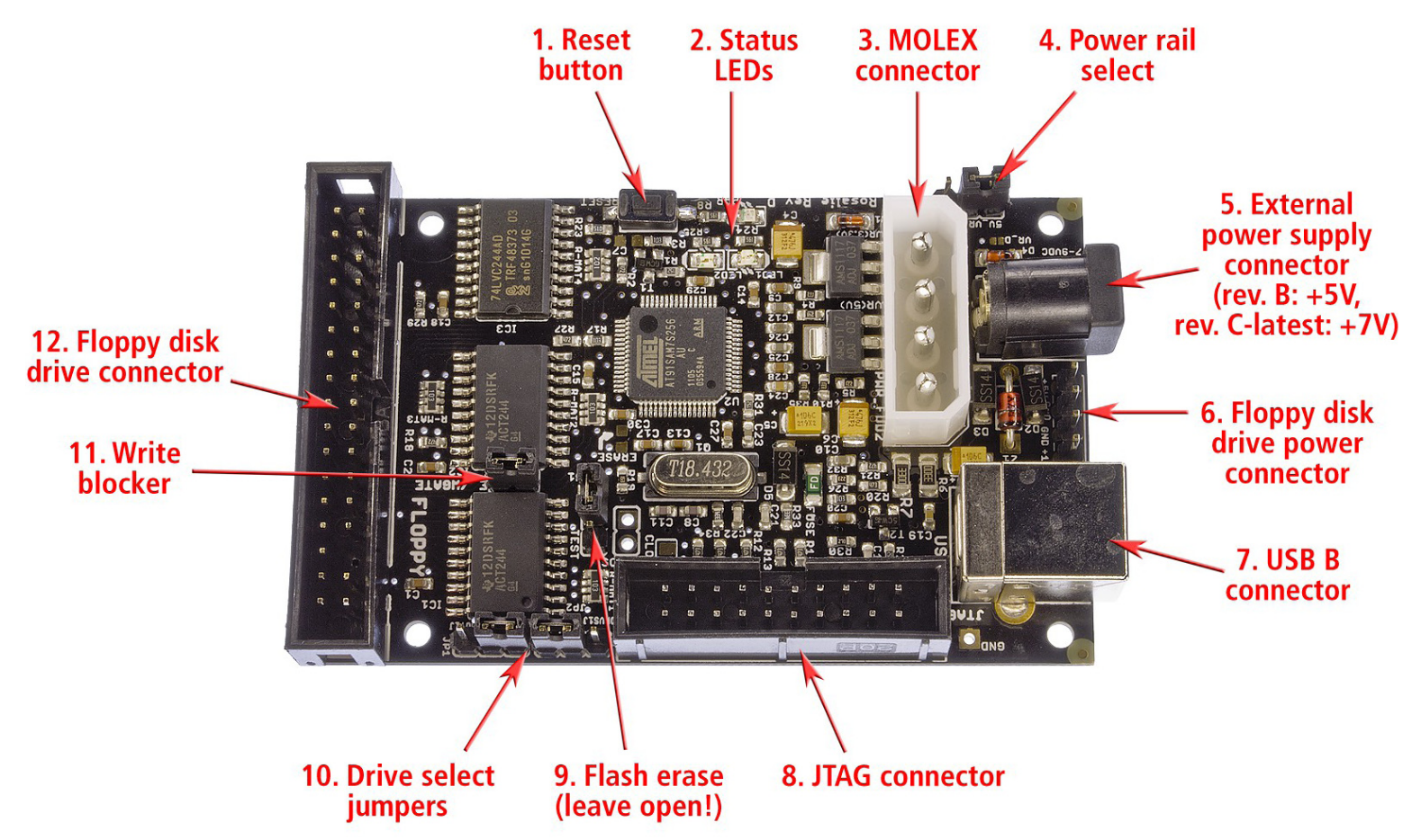
(1) Reset button: If the board does not function or hangs after usage, press this button to reset the board.
(2) LEDs: There are three LEDs on the board. The LED on the upper right (red) should light up all the time when the unit is on. The LEDs to the lower left and right (yellow and green) are off as long the unit has not been used in a session. As soon as the firmware has loaded, the LEDs start to fade alternatingly. The green LED signals firmware activity, while the yellow one indicates an active USB connection.
(3) MOLEX power connector: KryoFlux is a fully bus powered device. Therefore no external power is needed. For special purposes the board allows to be powered externally. It is even possible to distribute power to an attached device (see 5.). Please note that the power rail for +5V is directly connected to the device’s CPU. A bad (cheap, unreliable, broken) power supply can damage your board as well as external devices. The PSU must deliver a minimum of 1A per power rail (+5V/+12V). Check the orientation before attaching the plug. Incorrect orientation of the cable will DESTROY your KryoFlux board and/or your drive. You will also void your warranty (prebuilt boards).
(5) DC power connector: Standard power connector to supply +5V (rev. B board) or +7 to +9V (rev. C board and later; will internally be transformed to +5V) DC to the board (if desired). Useful when powering a 3.5” drive through the board, as these usually don’t need +12V. The PSU must deliver a minimum of 1A, tip is hot, shield is ground. Do not connect more than +5V DC to a rev. B board or more than +9V DC to a rev. C (or later) board! You will destroy the board and other equipment as well. You will also void your warranty.
(6) Berg power connector to power a drive – or two with y-cable – via the board: You must use standard Berg connectors (also – incorrectly – referred to as Molex mini) to connect the drive to the board. On the picture above, +12V DC is to the bottom, so the yellow cable of the connector MUST face to the bottom as well, with the red cable facing up (+5V DC). Incorrect orientation of the cable will DESTROY your KryoFlux board and/or your drive! You will also void your warranty (prebuilt boards).
(7) USB B connector: KryoFlux connects to the computer with a USB A to USB B plug. The board (NOT an attached drive!) is solely powered through USB.
(8) JTAG connector (not used): This connector is for development purposes and advanced servicing only and can be ignored.
(9) Firmware erase jumper: KryoFlux uses an ATMEL CPU as the core of its system and can be booted from internal flash memory. KryoFlux does not flash firmware onto the device. Instead, it is downloaded at the beginning of each session (it’s so fast, you won’t even notice). If some other application accidentally writes something into the flash, unplug the device. Set the erase jumper to on. Connect the device, wait at least ten seconds. Now unplug the device and set the jumper to off again. KryoFlux is now back to normal.
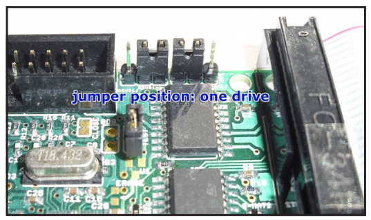
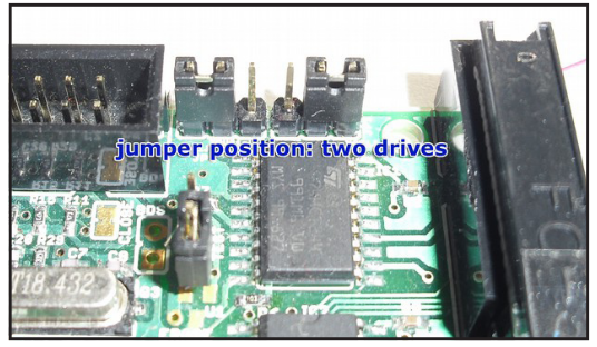
(10) Drive select jumpers: Floppy cables usually have two sections for connecting drives, each of them has two connectors (one for 3.5” drives, the other one for 5.25” drives). You must only connect one drive to one section at a time. The section where the cable is twisted over (at the very end of the cable) is for drive 0 (which used to be drive A: in PCs). The other section is for drive 1 (which used to be drive B: in PCs).
(12) Floppy disk drive connector: This socket is for the other end of the drive cable. If it has a small nose, make sure its orientation matches the gap in the socket. If not, please check for pin 1, which is marked. Make sure line 1 (usually signalled by a colored cable) is pointing towards the drive select jumpers (no. 8).
Power rail select:
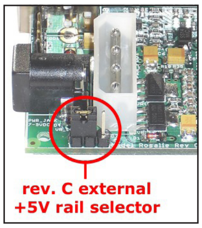
Revision C and later of the KryoFlux board come with a regulated external +5V power rail. All external power that is fed into the board via the MOLEX (3) and DC power (4) connector is regulated for a stable +5V DC power supply. This can come in handy for special usage scenarios and will also ensure that the bus driver ICs are operated at precisely +5V. While the DC power connector is always regulated (therefore rev.C boards or later need +7V to +9V DC present at the DC power connector), the routing from the MOLEX connector can be adjusted via a jumper. The setting on the left will transform +12V to precisely +5V. The opposite setting will route +5V or whatever is present at the +5V rail of the MOLEX connector. This rail has no protection diode, so be sure to not experiment with polarity. More than +5V DC or wrong polarity will fry your board! We recommend keeping the jumper at the position shown on the picture at all times.
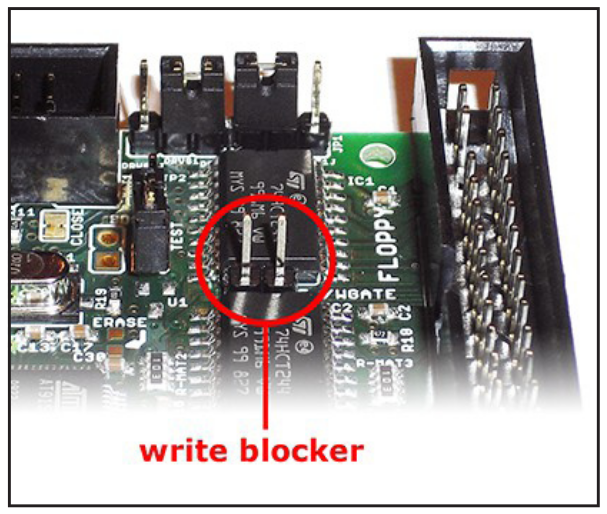
(11) Write blocker: With the introduction of writing to the KryoFlux host software (DTC) and firmware, protection of media on the hardware level became necessary. The commercial marketplace offers special devices that can be put between a floppy disk drive and a controller to prevent accidential writes. This functionality has been added to the KryoFlux hardware.
Revision D and later offer a built-in write blocker. The write block can be enabled by removing the jumper for WRITE GATE. After it has been removed KryoFlux can not write to disk, regardless of media and protection tab. Putting the jumper in place will enable writing again. The picture shows the board with the write block enabled. If you are using KryoFlux in a preservation environment at an archive, library or museum we strongly recommend setting this jumper as shown. This setting can not be circumvented in software.
Using a so-called “flippy”-modified floppydrives
There currently exists two versions of this modification/drive:
Version #1 (“Panasonic”) works by modifying the drive so that it can step into the negative domain and access a virtual track -8 on the upper head – which is the location of track 0 of a “flipped disk” written with a single headed drive. Note: During a dump you’ll see a message that says “00.0 : Control Command Rejected by the Device” - When you see this, it means the read/write head has moved to the normal side (see below) of the track 0 sensor. This drive can also be used like a standard drive with a standard controller as well.
Version #2 (“Teac”, “Newtronics”) works by re-aligning track 0 to -8, meaning that it is permanently track-shifted, so data read off standard disks will need to be adjusted in software. Version #2 drive does therefore no longer work with a standard controller. Since the Teac and Newtronics do not bypass the track 0 sensor, neither are prone to getting stuck in the negative domain.
| WARNING
Floppy disk drives tend to self-initialize at powerup, e.g. by doing a seek to track 0, which will activate the track 0 sensor (“/TRK00”). When using version #1 disk drives, stopping a dumping process while the drive is below track 0 (reading between -8 and -1) will leave the drive in an undefined position. If the drive is left undefined, the next access (with a seek for track 0) will move the head further back (“outwards”) until it reaches a mechanical barrier. This will result in “banging”, a loud rattling sound, which might misalign or further damage the drive. If you hear such sound, remove power immediately. The drive can then be carefully repositioned by turning the motor spindle which moves the head. DO NOT PUSH the head carriage itself! NOTE: Starting from DTC version 2.72, if the dumping process is interrupted by means of software (ie. ctrl + c), the head carriage will be repositioned back to track 0 regardless of its current position. ersion #1 drive must be the only device on the Shugart bus (=connected to KryoFlux) OR any other drive connected (only one modified drive per bus) must not have contact to pin 33 (usually ground, used here for TRK00 bypass). Also, regardless of what the manual might say, KryoFlux must be powered (=connected to USB) before the drive itself is powered. Otherwise track 0 might become “invisible” for the drive. In both scenarios the drive will bang its head against the mechanical barrier trying to find track 0. |
Note: This drive is by definition to be used with the KryoFlux floppy disk controller only. Chances are that, depending on brand and model, the drive will work with other controllers. However, such operation cannot be guaranteed.
Drive can be connected to the KryoFlux with the supplied (if bought with a KryoFlux) or a standard floppy disk data cable. Please note that the data connector on the PCB has a marking for data line #1 which must be aligned with the red (or otherwise coloured) stripe of the data cable. As outlined above, Version #1 must be the only drive on the bus or any other drive must not connect to data line 33 of the drive data cable, as this signal is used to control the negative track stepping feature.
Damage caused by scenarios outlined above is exempt from warranty.

